flowchart TD
    A[Loadbang] --> B[File Loading]
    B --> C[Soundfiler]
    C --> D[Array Storage]
    D --> E[Sample Count]
    F[Start Slider] --> G[Position Calculation]
    H[Stop Slider] --> G
    I[Speed Slider] --> J[Duration Calculation]
    E --> K[Sample Index Conversion]
    G --> K
    J --> L[Interpolation Parameters]
    K --> L
    M[Play Button] --> N[Line~ Object]
    L --> N
    N --> O[Tabread4~]
    D --> O
    O --> P[Audio Output]
3 Rec & Play
In this chapter, we will explore the relationship between recording and playback. We will look at how these two processes can be used to create new sounds and compositions. We will also discuss the technical aspects of recording and playback, including the equipment and techniques used in the process. We will also consider the artistic implications of recording and playback, including how these processes can be used to create new forms of expression and communication.
3.1 Simple Audio Player
The simple audio player represents a streamlined approach to audio file playback that emphasizes ease of use while providing essential control over playback parameters. This Pd implementation demonstrates how to create an intuitive audio player interface that combines file loading, visual feedback, and precise playback control in a single cohesive system. The patch showcases fundamental concepts including automatic file loading, visual waveform display, start/stop position control, playback speed manipulation, and smooth parameter interpolation.
3.1.1 Patch Overview
The simple audio player patch implements a user-friendly playback system that automatically loads an audio file into a visual array and provides comprehensive control over playback parameters through an intuitive slider-based interface. The patch operates by calculating playback positions based on normalized start and stop points, which are then converted to sample-accurate indices for precise audio retrieval. The architecture emphasizes visual feedback through multiple display elements that show both the raw sample data and the calculated playback parameters in real-time.
The design centers around immediate usability, where a single "play!" button triggers playback of a predefined segment with user-controlled speed and timing parameters. The visual interface provides dual representation of the audio content through both a large waveform display that shows the entire audio file and smaller numeric displays that provide precise feedback on calculated values. The playback engine employs interpolated table reading to ensure high-quality audio reproduction across all speed settings, while the parameter calculation system converts user-friendly interface values into the sample-accurate indices required for proper audio playback.
The patch incorporates automatic initialization through a loadbang that ensures the audio file is loaded immediately when the patch opens, eliminating the need for manual file loading procedures. The control system provides independent manipulation of start position, stop position, playback speed, and interpolation timing, with all parameters working together to create a flexible and responsive playback environment suitable for both educational exploration and practical audio playback applications.
3.1.2 Data Flow
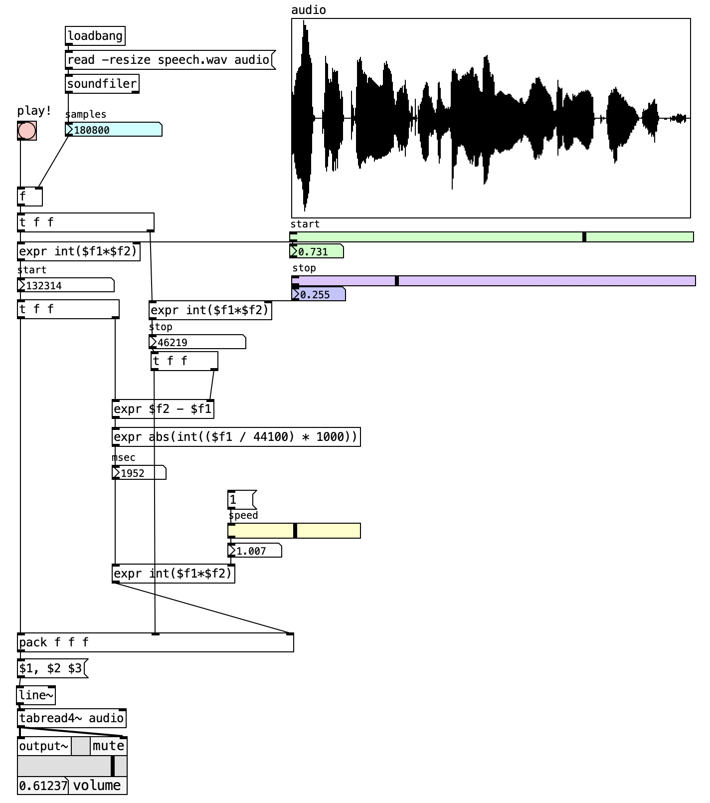
The audio player system begins its operation with an automatic initialization sequence triggered by the loadbang object at patch startup. This initialization sends a message to the soundfiler object instructing it to load the file “speech.wav” into the “audio” array with automatic resizing enabled. The soundfiler responds by reading the entire audio file into the array and returning the total number of samples, which becomes the fundamental reference value for all subsequent position and timing calculations. This sample count is immediately displayed in a numeric box and distributed throughout the system to serve as the basis for converting normalized slider positions into actual sample indices.
The position control system operates through two horizontal sliders that represent the start and stop positions as normalized values between 0 and 1. These normalized positions are processed through expression objects that multiply them by the total sample count, converting the user-friendly slider positions into precise sample indices that correspond to actual locations within the audio file. The start position calculation uses the expression int($f1*$f2) where the first input is the normalized slider value and the second is the total sample count, ensuring that the resulting index points to an exact sample location within the array.
The timing and speed control mechanism calculates the duration and interpolation parameters necessary for smooth playback transitions. The duration calculation subtracts the start sample index from the stop sample index using the expression $f2 - $f1, providing the total number of samples that will be played during the current playback segment. This duration value is then converted from samples to milliseconds using the expression abs(int(($f1 / 44100) * 1000)), which divides by the standard sample rate and multiplies by 1000 to produce a time value suitable for the interpolation system.
The speed control system modifies the calculated duration by multiplying it with the speed slider value through the expression int($f1*$f2). This calculation allows users to control playback speed, where values less than 1 produce slower playback and values greater than 1 produce faster playback. The resulting modified duration becomes the interpolation time parameter that determines how quickly the playback position moves from the start index to the stop index.
When the "play!" button is triggered, all calculated parameters are combined into a message that drives the line~ object. The pack f f f object consolidates the start position, stop position, and interpolation time into a single list, which is then formatted by a message object into the proper syntax for the line~ object. This formatted message instructs the line~ to smoothly interpolate from the start sample index to the stop sample index over the calculated time duration, creating a continuously changing index value that scans through the selected portion of the audio file.
The final audio generation stage employs the tabread4~ object to retrieve audio samples from the array using the continuously changing index values provided by the line~ object. The fourth-order interpolation ensures smooth audio reproduction even when the playback speed produces non-integer index values or when rapid parameter changes occur. The interpolated audio output is then routed to the output~ object for final amplification and speaker routing, completing the signal path from stored audio data to audible output.
3.1.3 Key Objects and Their Roles
| Object | Purpose |
|---|---|
soundfiler |
Loads audio files into arrays and reports sample count |
array audio |
Stores audio waveform data with visual display |
tabread4~ |
Performs interpolated audio reading from the array |
line~ |
Generates smooth ramp signals for position scanning |
pack f f f |
Combines start, stop, and time parameters |
expr |
Performs mathematical calculations for position and timing |
output~ |
Provides stereo audio output with level control |
The patch demonstrates several key Pd programming concepts, including automatic patch initialization through loadbang, visual array management for waveform display, mathematical expression evaluation for parameter conversion, and smooth audio-rate interpolation for high-quality playback. The modular design separates user interface elements from audio processing components, making the system easy to understand and modify. This implementation serves as an excellent foundation for understanding basic audio playback principles and can be easily extended with additional features such as looping, multiple file support, or external control integration. The visual feedback provided by the waveform display and numeric readouts makes it particularly suitable for educational applications where understanding the relationship between interface controls and audio parameters is important.
3.1.4 Creative Applications
- Extreme time stretching: Push the speed control to very low values (0.1 or lower) to create drone-like textures from short audio snippets
- Rhythmic patterns: Use rapid speed changes and phase jumps to generate percussive sequences from sustained tones
- Reverse archaeology: Load full songs and use reverse playback to discover hidden melodic content and create backwards reveals
- Granular-style effects: Combine fast phase position changes with short loop lengths to simulate granular synthesis behaviors
- Live performance tools: Map MIDI controllers to speed and phase parameters for real-time manipulation during performances
- Micro-sampling: Load very short sounds (vocal consonants, instrument attacks) and stretch them to reveal internal acoustic details
- Rhythmic displacement: Sync multiple samplers to the same clock but with different phase offsets to create polyrhythmic patterns
3.2 Audio Sampler with [phasor~]
The audio sampler represents a fundamental tool in digital audio processing and musical performance, enabling the capture, manipulation, and playback of recorded audio material. This Pd implementation demonstrates how to create a comprehensive sampling system that provides real-time control over playback speed, direction, position, and interpolation. The patch showcases essential concepts including array-based audio storage, variable-speed playback, phase control, and temporal interpolation for smooth parameter transitions.

3.2.1 Patch Overview
The audio sampler patch implements a playback engine that reads audio data from a table array and provides extensive real-time control over the playback parameters. The system operates by using a phasor oscillator to generate index values that scan through the stored audio samples, with multiplication factors applied to control playback speed and direction. The architecture supports both forward and reverse playback, variable speed control ranging from extreme slow motion to high-speed acceleration, and precise positioning within the audio material.
The design follows a modular approach where audio loading, parameter control, and playback generation are handled by distinct subsystems that communicate through Pd’s send and receive mechanism. The audio storage system utilizes a resizable array that automatically adjusts to accommodate different audio file lengths, while the playback control provides independent manipulation of speed, direction, interpolation time, and starting position. The output stage employs interpolated table reading to ensure smooth audio reproduction even during rapid parameter changes or extreme speed variations.
The interface provides immediate visual feedback through horizontal sliders for speed control, interpolation time adjustment, and phase positioning, along with numeric displays that show the current playback parameters and array position. This design enables both precise manual control and potential automation through external control sources, making it suitable for live performance, sound design, and experimental audio manipulation applications.
3.2.2 Data Flow
flowchart TD
    A[Audio File Loading] --> B[Soundfiler Object]
    B --> C[Array Resize]
    C --> D[Sample Count Storage]
    E[Speed Control] --> F[Direction Multiplier]
    F --> G[Interpolation System]
    G --> H[Phasor Generation]
    I[Phase Position] --> H
    J[Sample Rate] --> K[Rate Calculation]
    D --> K
    K --> L[Base Frequency]
    L --> H
    H --> M[Table Reading]
    M --> N[Audio Output]
The patch begins its operation with the audio loading process, initiated by a message that triggers the soundfiler object to read an audio file into the designated array. The soundfiler automatically resizes the array to match the audio file length and returns the total number of samples, which is stored and distributed to other components through the send/receive objects. This sample count becomes crucial for calculating appropriate playback rates and ensuring the phasor oscillator operates within the correct frequency range.
The speed and direction control processes user input from the horizontal slider, which provides values ranging from -5 to +5, representing both playback speed and direction. Negative values produce reverse playback, while positive values generate forward playback, with the magnitude determining the speed multiplier. This control value is processed through an interpolation that uses the line object to create smooth transitions between different speed settings, preventing audible artifacts that might occur from abrupt parameter changes.
The core playback engine centers around a phasor~ oscillator that generates a continuously increasing ramp signal from 0 to 1. The frequency of this phasor is calculated by dividing the current sample rate by the total number of samples in the array, then multiplied by the speed control factor. This calculation ensures that a speed setting of 1 produces normal playback rate, while other values create proportional speed changes. The phasor output is then scaled to match the array size, creating index values that span the entire audio content.
The phase position control provides an additional layer of playback manipulation by allowing users to offset the starting position within the audio material. This parameter is multiplied with the scaled phasor output, enabling jumps to specific locations within the audio file or creating loop-like behaviors when combined with appropriate speed settings. The position control operates independently of the speed system, allowing for complex playback patterns and non-linear audio exploration.
The final playback stage employs the tabread4~ object, which performs fourth-order interpolated reading from the audio array. This interpolation method ensures smooth audio reproduction even when the playback speed produces non-integer index values or when rapid parameter changes occur. The interpolated output maintains audio quality across the full range of speed and position manipulations, providing professional-grade sample playback capabilities.
Real-time monitoring and feedback systems track the current playback position and convert it to visual representations through the horizontal slider display and numeric readouts. The unsig~ objects convert audio-rate signals to control-rate values suitable for interface updates, while the positioning system provides continuous feedback about the current location within the audio material.
3.2.3 Key Objects and Their Roles
| Object | Purpose |
|---|---|
soundfiler |
Loads audio files into arrays and reports sample count |
tabread4~ |
Performs interpolated audio reading from the array |
phasor~ |
Generates scanning ramp signal for array indexing |
array sampler |
Stores audio data with automatic resizing capability |
expr $f2 / $f1 |
Calculates base playback rate from sample count and sample rate |
line |
Provides smooth interpolation between parameter changes |
pack f f |
Combines value and interpolation time for line object |
samplerate~ |
Reports current system sample rate |
unsig~ |
Converts audio-rate signals to control-rate values |
s / r |
Send and receive objects for parameter distribution |
*~ |
Multiplies audio signals for speed and direction control |
output~ |
Provides stereo audio output with level control |
This implementation serves as a foundation for more complex sampling applications, including granular synthesis, multi-sample instruments, and advanced audio manipulation tools. The real-time control capabilities make it suitable for live performance contexts, while the precise parameter control enables detailed studio work and sound design applications.
3.2.4 Creative Applications
- Create rhythmic patterns: Use rapid speed changes and phase jumps to generate percussive sequences from sustained tones
- Granular-style effects: Combine fast phase position changes with short loop lengths to simulate granular synthesis behaviors
- Live performance tools: Map MIDI controllers to speed and phase parameters for real-time manipulation during performances
- Sound design layers: Layer multiple instances with different source materials and speed relationships to create complex evolving textures
- Micro-sampling: Load very short sounds (vocal consonants, instrument attacks) and stretch them to reveal internal acoustic details
- Rhythmic displacement: Sync multiple samplers to the same clock but with different phase offsets to create polyrhythmic patterns
3.3 I’m Sitting in a Room – Alvin Lucier
I’m Sitting in a Room (Alvin Lucier) consists of a 15-minute and 23-second sound recording. The piece opens with Lucier’s voice as he declares he is sitting in a room different from ours. His voice trembles slightly as he delivers the text, describing what will unfold over the next 15 minutes:
“…I am recording the sound of my speaking voice and I am going to play it back into the room again and again…”
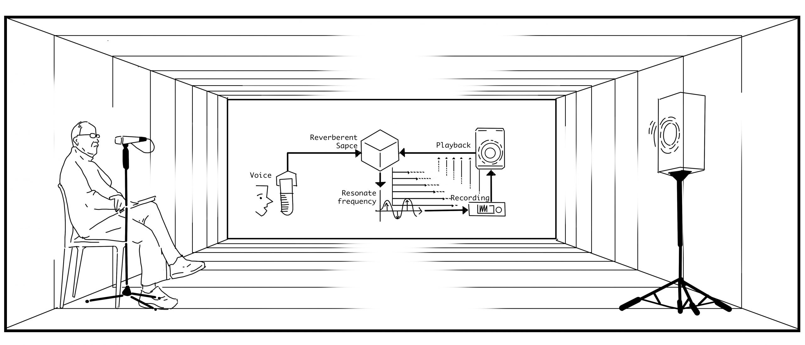
As listeners, we know what is going to happen, but we don’t know how it will happen (Hasse 2012). We listen, following Lucier’s recorded voice. Then, Lucier plays the recording into the room and re-records it. This time, we begin to hear more of the room’s acoustic characteristics. He continues to play back and re-record his voice—over and over—until his speech becomes softened, almost dissolved, into the sonic reflections of the room in which the piece was recorded and re-recorded.
One effective way to study a piece is to replicate its technical aspects and the devices involved. The aim of this activity is to recreate the technical setup of I’m Sitting in a Room, focusing on the processes of recording, playback, and automation.
There are many ways to implement this technical system. Just to mention two environments we’re currently working with: it’s relatively straightforward in Pd. In terms of hardware, you’ll need:
| Hardware Component | Specification | Purpose |
|---|---|---|
| Computer | Any computer capable of running Pd | Host system for running the patch |
| Speaker | Mono audio output | Plays back recorded audio into the room |
| Microphone | Mono audio input | Captures audio from the room |
| Room | Semi-reverberant acoustic space | Provides natural acoustic reflections and resonances |
The system should include at least two manual (non-automated) controls:
- Start recording
- Stop recording
Choose a room whose acoustic or musical qualities you’d like to evoke. Connect the microphone to the input of tape recorder #1. From the output of tape recorder #2, connect to an amplifier and speaker. Use the following text, or any other text of any length:
I am sitting in a room different from the one you are in now. I am recording the sound of my speaking voice, and I am going to play it back into the room again and again until the resonant frequencies of the room reinforce themselves so that any semblance of my speech, with perhaps the exception of rhythm, is destroyed. What you will hear, then, are the natural resonant frequencies of the room articulated by speech. I regard this activity not so much as a demonstration of a physical fact, but more as a way to smooth out any irregularities my speech might have.
The following steps outline the process:
- Record your voice through the microphone into tape recorder #1.
- Rewind the tape, transfer it to tape recorder #2, and play it back into the room through the speaker. - Record a second generation of the statement via the microphone back into tape recorder #1.
- Rewind this second generation to the beginning and splice it to the end of the original statement in tape recorder #2.
- Playback only the second generation into the room and record a third generation into tape recorder #1.
- Continue this process through multiple generations.
All the recorded generations, presented in chronological order, create a tape composition whose duration is determined by the length of the original statement and the number of generations produced. Make versions in which a single statement is recycled through different rooms. Create versions using one or more speakers in different languages and spaces. Try versions where, for each generation, the microphone is moved to different parts of the room(s). You may also develop versions that can be performed in real time.
3.3.1 Pd implementation of I’m sitting in a room
This patch is inspired by Alvin Lucier’s iconic piece and demonstrates how to recursively record and play back sound to reveal the resonant frequencies of a room.
3.3.2 Patch Overview
The Pd implementation of I’m Sitting in a Room creates a digital recreation of Alvin Lucier’s seminal work through a carefully orchestrated system of recording, playback, and re-recording processes. This patch demonstrates how computational tools can faithfully reproduce the acoustic phenomena that drive Lucier’s piece, where the gradual accumulation of room resonances transforms speech into pure acoustic space. The implementation leverages Pd’s audio file handling capabilities, signal routing architecture, and user interface elements to create an interactive environment that allows users to experience the recursive transformation process in real-time.
The system architecture revolves around a dual-recording mechanism that alternates between two separate audio files, mimicking the original tape recorder setup used in Lucier’s piece. This alternating approach ensures that each generation of the recording process builds upon the previous one, creating the cumulative acoustic effect that defines the work. The patch employs a signal routing system that uses Pd’s send and receive objects to distribute audio signals to multiple destinations simultaneously, enabling the concurrent processes of playback monitoring and re-recording that are essential to the piece’s realization.
3.3.3 Data Flow
The following diagram illustrates the recursive nature of the recording and playback process, similar to how Lucier’s piece unfolds. Each generation of tape recorders captures the previous one, creating a feedback loop that emphasizes the room’s resonances.
flowchart TB
  %% Top level source
  Input[Microphone]

  subgraph PLAYBACK RECORDERS
    direction LR
    subgraph RecorderA [DEVICE A]
      RecordA[Record A.wav]
      PlayA[Play A.wav]
      RecordA -.-> PlayA
    end

    subgraph RecorderB [DEVICE B]
      RecordB[Record B.wav]
      PlayB[Play B.wav]
      RecordB -.->PlayB
    end
  end

  %% Output at the bottom
  Output((Speaker))

  %% Clear connections showing signal flow
  start([1-start]) --> RecordA
  stop([2-stop]) --> RecordA
  stop([2-stop]) --> RecordB
  stop([2-stop]) --> PlayA

  Input ==> RecordA
  Input ==> RecordB

  PlayA ==> Output
  PlayB ==> Output

  %% Feedback path showing recursion
  PlayB -.->|"Trigger to<br> start recording"| RecordA
  PlayA -.->|"Trigger to<br> start recording"| RecordB
  Output ==> room["ROOM'S<br>REFLECTIONS"]:::roomStyle ==> Input

  classDef roomStyle fill:#f5f5f5,stroke:#333,stroke-dasharray:5 5
The following sequence diagram illustrates the process of recording and playback in the patch. It shows how the audio input is captured, recorded, played back, and re-recorded in a loop, emphasizing the room’s resonances.
sequenceDiagram
    participant Start as Start
    participant Stop as Stop
    participant Input as Mic
    participant RecA as Rec A.wav
    participant PlayA as Play A.wav
    participant RecB as Rec B.wav
    participant PlayB as Play B.wav
    participant Output as Speaker
    participant Room as Room

    %% Generation 1
    activate Input
    Start-->>RecA: Start button
    activate RecA
    Input->>RecA: Mic input


    Stop--xRecA: Stop Rec A
    deactivate RecA
    Stop-->>RecB: Start Rec B
    activate RecB
    Input->>RecB: Mic input
    Stop-->>PlayA: Start Play A
    activate PlayA

    PlayA->>Output: Playback A.wav
    Output->>Room: Acoustic Space
    Room->>Input: Acoustic reflections captured
    PlayA--xRecB: Trigger Stop Rec B
    deactivate RecB
    deactivate PlayA

    PlayA-->>RecA: Trigger Start Rec B
    activate RecA
    Input->>RecA: Mic input
    PlayA-->>PlayB: Trigger Start Play A
    activate PlayB

    %% Generation 2
    PlayB->>Output: Playback B.wav
    Output->>Room: Acoustic Space
    Room->>Input: Acoustic reflections captured

    %% Generation 3 (process repeats)
    PlayB--xRecA: Trigger Stop Rec A
    deactivate RecA
    deactivate PlayB
    PlayB-->>RecB: Trigger Start Rec B
    activate RecB
    Input->>RecB: Mic input
    PlayB-->>PlayA: Trigger Start Play A
    activate PlayA
    PlayA->>Output: Playback
    Output->>Room: Acoustic Space
    Room->>Input: Acoustic reflections captured

    Note over Input,Room: The process continues, alternating between devices and reinforcing the room's resonances.
    deactivate Input
    deactivate PlayA
    deactivate RecB
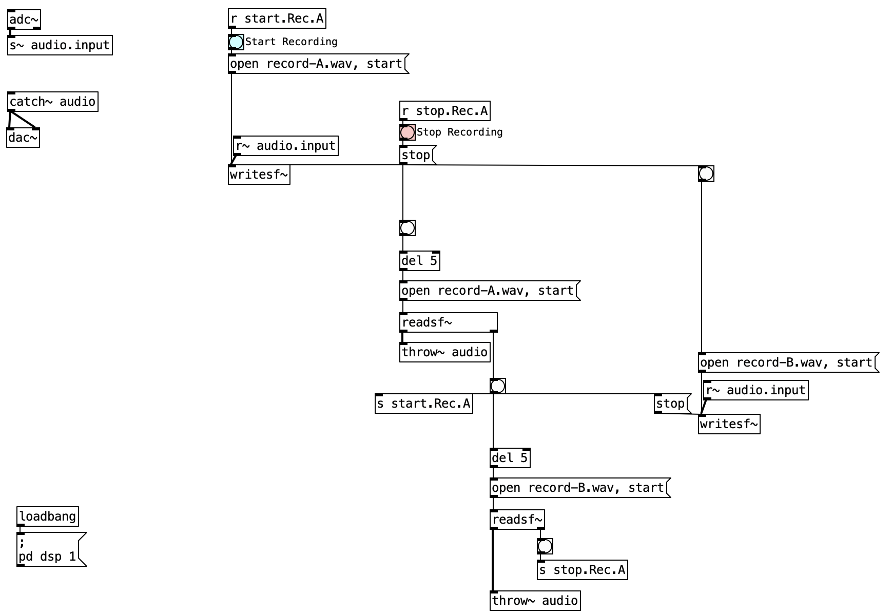
The I’m Sitting in a Room patch operates through a carefully orchestrated sequence of recording, playback, and re-recording phases that mirror Alvin Lucier’s original tape-based methodology. The system begins with audio input acquisition, where live microphone signals from the adc~ object are immediately routed through the s~ audio.input send object to distribute the audio signal to multiple destinations within the patch. This centralized routing approach ensures that the same input signal can be simultaneously monitored and recorded without creating feedback loops or signal conflicts.
The initial recording phase commences when the user triggers the “Start Recording” button, which sends a message to open and start recording to record-A.wav through the first writesf~ object. The audio content is captured from the r~ audio.input receive object, ensuring that whatever audio is currently being input to the system—whether live microphone input or processed audio from previous generations—is properly recorded to the designated file. The recording process continues until the user manually triggers the “Stop Recording” button, which sends a stop message to terminate the current recording session and prepare the system for the next phase of operation.
Upon stopping the initial recording, the patch automatically initiates the first playback and re-recording cycle through a carefully timed sequence of operations. The stop message triggers a bang that, after a brief delay implemented through the del 5 object, opens and begins playing record-A.wav through the readsf~ object. Simultaneously, this same trigger initiates the recording process for the second generation by opening record-B.wav and starting the second writesf~ object. The audio from the playback is routed through the throw~ audio object for real-time monitoring while also being sent to the r~ audio.input pathway, where it becomes the source material for the next recording generation.
The alternating recording mechanism forms the core of the recursive process, where each generation of recorded material becomes the source for the subsequent recording. When record-A.wav is played back, its audio content is automatically captured and recorded to record-B.wav. Upon completion of this recording cycle, the process reverses: record-B.wav is played back while record-A.wav is re-recorded with the processed audio content. This alternating pattern continues indefinitely, with each generation accumulating more of the room’s acoustic characteristics and gradually transforming the original speech content into pure room resonance.
The timing and synchronization system ensures smooth transitions between recording and playback phases through a network of interconnected bang objects and delay objects. When a recording session ends, the resulting bang signal triggers multiple simultaneous actions: stopping the current recording, initiating the playback of the just-recorded file, and beginning the recording of the next generation. The del 5 objects provide brief delays that prevent timing conflicts and ensure that file operations complete properly before subsequent operations begin. This timing mechanism is crucial for maintaining the integrity of each generation and preventing data corruption during the file switching operations.
The monitoring and output system allows users to hear the transformation process in real-time through the throw~ and catch~ audio objects, which collect audio signals from whichever playback operation is currently active. The catch~ audio object serves as a central mixing point that combines all active audio signals and routes them to the dac~ object for speaker output. This real-time monitoring capability is essential for understanding how the acoustic transformation unfolds over successive generations, allowing users to hear the gradual dissolution of speech content and the emergence of pure room resonance patterns.
The patch initialization and control ensures proper startup conditions through a loadbang object that automatically enables DSP processing when the patch opens. The control interface provides clearly labeled buttons for starting and stopping recordings, with visual feedback through the bang objects that indicate when various operations are triggered. The send and receive network (s start.Rec.A, r start.Rec.A, s stop.Rec.A, r stop.Rec.A) provides centralized control over the recording processes, allowing multiple parts of the patch to coordinate their operations without creating complex direct connections that would make the patch difficult to understand and maintain.
3.3.4 Key Objects and Their Roles
| Object | Purpose |
|---|---|
adc~ |
Audio input from microphone |
writesf~ |
Record audio to a file |
readsf~ |
Play audio from a file |
throw~/catch~ |
Mix and route audio signals |
dac~ |
Audio output to speakers |
3.3.5 How to Use the Patch
- Start Recording:
Click the “Start Recording” button and speak or make a sound. - Stop Recording:
Click the “Stop Recording” button to finish. - Playback and Re-record:
Use the playback button to play your recording into the room and simultaneously re-record it. - Repeat:
Repeat the playback and re-recording process as many times as you like to hear the room’s resonances emerge.
3.4 I am sitting in a [freeverb~]
The patch example extends the original I am sitting in a room concept by introducing a virtual acoustic environment using reverb and allowing for pre-recorded audio input instead of just live microphone input. This adaptation provides more creative flexibility and consistent results compared to using a physical room.
This patch is designed to simulate the recursive recording process of Lucier’s piece while allowing for more control over the sound environment. It uses the freeverb~ object to create a virtual room effect, enabling you to manipulate the acoustic characteristics of the sound without relying on a physical space.
3.4.1 Patch Overview
The I am sitting in a [freeverb~] patch represents an digital adaptation of Alvin Lucier’s seminal work that replaces the physical acoustic environment with a controllable virtual room simulation. This implementation shows how creative coding can extend conceptual art practices by providing enhanced control over the recursive recording process while maintaining the essential transformative characteristics of the original piece. The patch architecture combines pre-recorded audio file playback capabilities with live input processing, allowing users to experiment with different source materials and acoustic environments without the constraints of physical room acoustics.
The system operates through a dual-recording mechanism that alternates between two audio files while applying cumulative reverb processing. This approach ensures that each generation builds upon the previous one’s acoustic characteristics, creating the progressive transformation that defines Lucier’s work. The patch employs a comprehensive signal routing system using Pd’s send and receive architecture to manage the complex interconnections between playback, processing, and recording components, enabling seamless transitions between generations without manual intervention.
3.4.2 Unique Features of the [freeverb~] Version
3.4.2.1 Audio File Input
Unlike the original patch that only uses microphone input, this version can:
- Play a pre-recorded audio file (
speech.wav) as the initial source - Process this file through reverb before recording
- Trigger playback with a button (labeled “2. Playback audio”)
flowchart LR
    bng([bng]) --> msg["msg open speech.wav, 1"]
    msg --> readsf["readsf~"]
    readsf --> freeverb["freeverb~"]
    freeverb --> send["s~ audio.input"]
3.4.2.2 Virtual Acoustic Environment
Instead of relying on a physical room’s acoustics, this patch uses freeverb~ objects to create a simulated acoustic space:
- Every audio signal (input and playback) passes through a
freeverb~object - This creates consistent reverberation that can be adjusted and controlled
- Multiple
freeverb~objects process different stages of the audio for cumulative effects
3.4.2.3 Enhanced Control Flow
The patch includes numbered controls for better workflow:
| Button | Label | Function |
|---|---|---|
| 1 | Start recording | Begins recording the input source to record-A.wav |
| 2 | Playback audio | Plays the speech.wav file through reverb into the system |
| 3 | Stop recording | Stops the current recording process |
3.4.2.4 Multiple Send/Receive Paths
The patch uses additional send/receive pairs to manage signal routing:
s~/r~ audio.input- Routes input signals to the recording objects~/r~ player.A- Routes playback from file A to recorder Bs~/r~ player.B- Routes playback from file B back to recorder Athrow~/catch~ audio- Collects all signals to be sent to the output
3.4.3 Data Flow
flowchart TB
  %% Top level source
  AudioFile[Audio File]

  %% Horizontal arrangement of recorders A and B
  subgraph PLAYBACK RECORDERS
    direction LR
    subgraph RecorderA [DEVICE A]
      RecordA[writesf~ A.wav]
      PlayA[readsf~ A.wav]
      RecordA ==> PlayA
    end

    subgraph RecorderB [DEVICE B]
      RecordB[writesf~ B.wav]
      PlayB[readsf~ B.wav]
      RecordB ==> PlayB
    end
  end

  subgraph VIRTUAL ROOM
  %% Reverb block in the middle
    VirtualRoom(((freeverb~<br>Virtual Room)))
  end

  %% Output at the bottom
  Output[dac~]

  %% Clear connections showing signal flow
  AudioFile --> RecordA
  AudioFile --> Output

  PlayA ==> VirtualRoom
  PlayB ==> VirtualRoom

  VirtualRoom ==> RecordB
  VirtualRoom ==> RecordA
  VirtualRoom --> Output

  %% Feedback path showing recursion
  PlayB -.->|"Trigger to<br> start recording"| RecordA
  PlayA -.->|"Trigger to<br> start recording"| RecordB
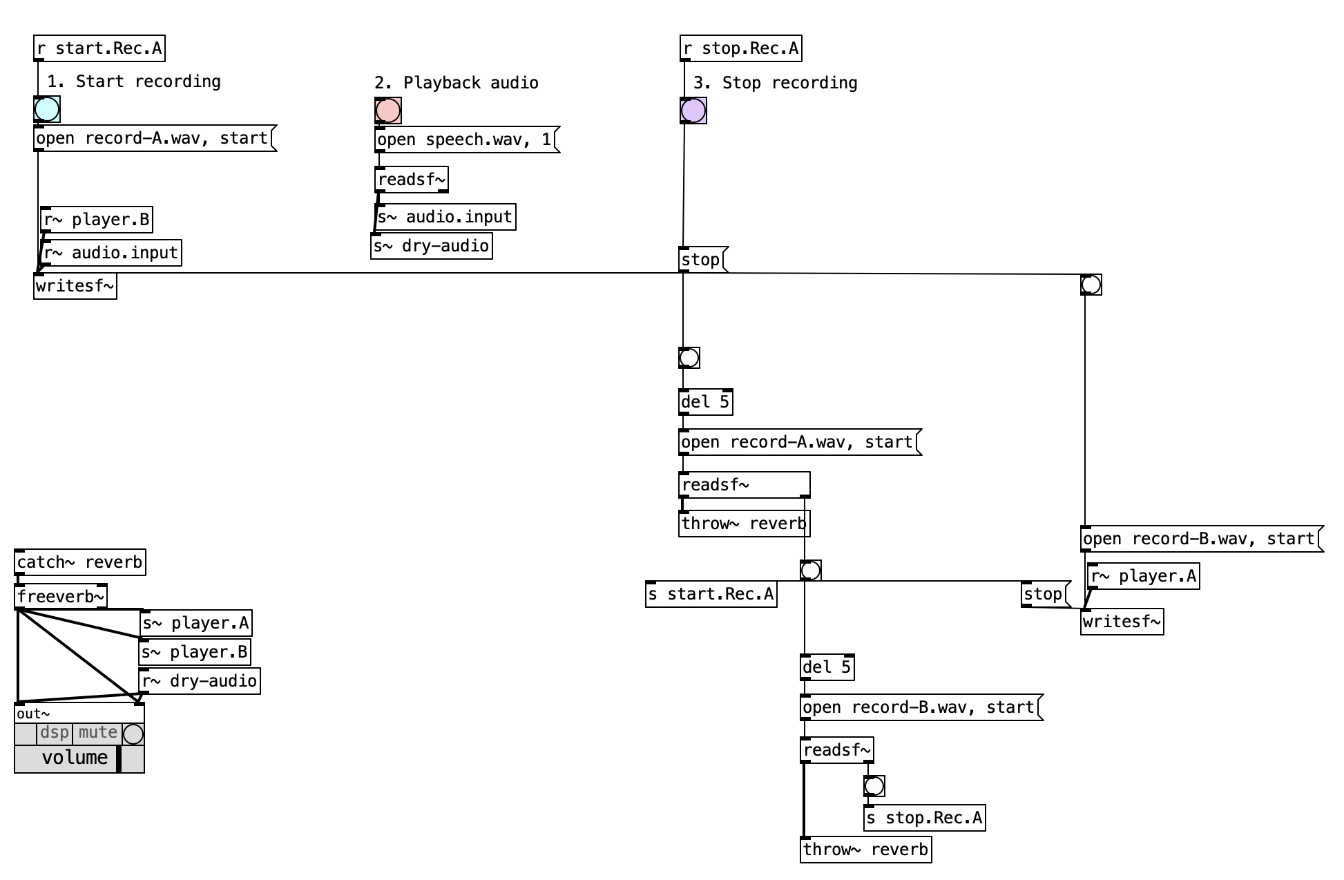
The operation of this patch begins with the establishment of initial audio source options, where users can choose between pre-recorded file input or live input sources. For pre-recorded file input, clicking the “2. Playback audio” button triggers the playback of speech.wav through a readsf~ object, which then processes the audio through freeverb~ before sending it to the s~ audio.input routing system. This approach provides consistent source material that can be used repeatedly for experimentation and comparison across different processing generations. While live input capability is not explicitly shown in this version, the architecture could easily accommodate an adc~ object that would capture real-time microphone input and route it through the same s~ audio.input pathway.
The recording of the first generation commences when the user clicks the “1. Start recording” button, which initiates the capture process to record-A.wav. The signal from s~ audio.input is captured by the corresponding r~ audio.input object and sent directly to a writesf~ object that handles the actual file writing operations. This resulting file contains the source material with initial reverb processing applied, establishing the foundation for subsequent generations. The recording process maintains the temporal structure and amplitude characteristics of the original material while introducing the first layer of artificial room acoustics that will be progressively enhanced through the recursive process.
The playback and re-recording phase begins automatically after stopping the initial recording with the “3. Stop recording” button. The patch executes a carefully orchestrated sequence where it opens and plays record-A.wav through another readsf~ object, processes this playback through an additional freeverb~ object for cumulative reverb effects, and then routes the processed signal along two parallel paths. The first path sends the audio to throw~ audio for real-time monitoring, allowing users to hear the progressive transformation as it occurs. The second path directs the same signal to s~ player.A, where it is received and simultaneously recorded to record-B.wav, creating the next generation of the recursive process.
The recursive process continues as each newly created recording becomes the source for the subsequent generation. When record-B.wav is created, it can be played back through its own readsf~ object, processed through yet another freeverb~ instance, and routed to both the monitoring system via throw~ audio and to s~ player.B for capture back to record-A.wav. This alternating cycle can continue indefinitely, with each generation accumulating more of the virtual room’s characteristics as defined by the freeverb~ parameters. The cumulative effect gradually transforms the original source material into a sonic representation of the artificial acoustic space, with the original speech or audio content becoming increasingly obscured while the rhythmic and temporal elements remain as the structural foundation.
The output stage serves as the central collection and distribution point for all audio signals in the system. All audio signals that have been sent to throw~ audio are collected by the corresponding catch~ audio object, which functions as a mixing bus that combines signals from whichever recording generation is currently active. This consolidated audio signal is then sent to an out~ object that handles the final output routing to speakers or headphones, ensuring that users can monitor the entire process in real-time and experience the gradual transformation as it unfolds through successive generations.
3.4.4 Key Objects Table
| Object | Purpose in This Patch |
|---|---|
freeverb~ |
Creates virtual room acoustics by adding reverberation |
readsf~ |
Plays audio files (source material or previous generations) |
writesf~ |
Records audio to file (for each generation) |
s~/r~ |
Routes audio between different parts of the patch |
throw~/catch~ |
Mixes and outputs all audio signals |
del |
Adds small delays to ensure proper sequencing of operations |
bng |
Provides buttons for user interaction |
out~ |
Sends audio to speakers/headphones |
3.4.5 Creative Applications
- Experiment with reverb settings: Try different room sizes, damping, and wet/dry mix
- Use different source materials: Test various speech samples, musical phrases, or sound effects
- Create hybrid processes: Record the first generation in a real room, then switch to the virtual environment
- Build compositional sequences: Layer different generations to create evolving textures
- Compare real vs. virtual: Process the same source through both the original and freeverb patches to contrast physical and virtual acoustics
This virtual approach offers a controlled laboratory for exploring the core concepts of Lucier’s piece, making it accessible even without an ideal acoustic space, while also opening new creative possibilities that wouldn’t be possible in a physical implementation.
References
Hasse, Sarah. 2012. “I Am Sitting in a Room.” Body, Space & Technology 11. https://doi.org/10.16995/bst.71.